Design the added depth before completing the façade
External Wall Insulation Crewe | Openings, Outlets and Finish
External wall insulation moves the finished face outward. That affects more than the appearance of the main wall: windows become more recessed, fittings may need extension and the roof and ground junctions need a suitable detail. A Crewe scheme should address those changes as part of the design, with render specified as the finish of a complete system. The proposal should explain suitability and scope before the owner is asked to approve colour and texture.

On this page
Assess the wall and the intended extent
The construction, condition and moisture-related issues need appropriate assessment. Existing defects should not be concealed simply because the new system will cover them. The proposal should identify which elevations are included and explain any partial treatment or transition to retained walls. The background must be suitable for the specified system and fixing design. If the property contains several constructions, the design should recognise those differences rather than assume a single visible colour means a single technical condition.
Render-only work and external insulation are different scopes. A house-rendering project may renew the covering without adding an insulation layer. The completed appearance can be similar, which makes the written description important. An insulation quote should name the full system and relevant thickness, not merely a decorative finish. Compare the associated alterations as well as the wall area so the owner understands what is included in the upgrade and what still belongs to another trade.
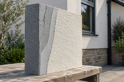
- Existing wall Prepared; fittings removed and the base track fixed above ground level.
- Insulation boards Bonded with adhesive and, in most systems, mechanically fixed to the wall.
- Basecoat with mesh Reinforcement mesh embedded across the board joints and around openings.
- Primer Where the system requires it.
- Finish render A thin-coat finish that weatherproofs the insulation.
Wall on the left, finish on the right. Not to scale: coats, thicknesses and primers follow the chosen manufacturer’s system and the condition of the wall.
Follow the new face around the openings
Sills, reveals and door details need to work with the added depth. Existing projections may require alteration, and opening lights must remain suitable for use. The design should identify the relevant components and the sequence with any window replacement. A sample of the final grain cannot demonstrate those changes. Drawings or clear details are needed so the renderer, window installer and other affected trades are working towards the same finished line.
At the roof perimeter, consider whether existing eaves or verge details remain suitable. At the bottom, the system must relate correctly to ground levels, drainage and the building's damp-proofing arrangement. These are design decisions, not cosmetic choices about how much of the old wall to hide. The appropriate detail depends on the construction and system. A generic instruction to continue the new face to the paving does not establish that the base arrangement is suitable.
| Interface | What the design needs to address |
|---|---|
| Windows and doors | Reveals, sill projections and operation |
| Roofline | Eaves, verges, gutters and abutments |
| Ground and base | Termination, drainage and damp-proofing relationship |
| Ventilation outlets | Function through the new wall depth |
| Pipes and fittings | Supports, extensions and weathering |
| Retained walls | A suitable transition at the system boundary |
Give ventilation and services their own schedule
Extractor outlets, air bricks, flues and other openings serve different functions. Their treatment should preserve the appropriate route and operation through the new thickness, with specialist involvement where required. The article on extractor outlets and insulation explains why a terminal cannot simply be buried or moved forward without considering the installation it serves. The rendering scope needs to connect with those specialist decisions before the final surface is formed.
Rainwater pipes, taps, lights and external equipment also need an agreed treatment. Known future attachments should be considered while suitable support and fixing details can be planned. Later alterations should follow the installed system's guidance rather than assume the face accepts ordinary fixings anywhere. The owner should retain the relevant information so maintenance contractors understand what lies beneath the render. An insulated façade remains a complete construction after installation, even when it looks like an ordinary coloured wall.
Keep the components within the specified system
The insulation, fixing arrangement, reinforcement, basecoat and finish should form the intended build-up. The proposal should identify it clearly and provide for any necessary substrate checks or technical review. Products should not be substituted casually because their individual descriptions appear similar. If a change is needed, it should be assessed and recorded through the appropriate route. The final colour is one choice within this specification, not the element that determines whether all the other components are suitable together.
A silicone finish may be available within the selected system, with other options depending on the specification. Approve a representative sample for appearance while keeping the technical build-up clear. Some checks need to happen before later layers conceal the relevant work. Agree those responsibilities and timing in advance. A final photograph of an attractive elevation cannot demonstrate every fixing, interface or preparation decision beneath it.
Sequence installation around the occupied property
Access, material storage and entrance protection should fit the site. Temporary removal of rainwater fittings or alterations to services may affect occupation, so explain those operations before they begin. The programme needs suitable conditions for the specified materials and the required intervals between stages. Other trades should complete their work at the agreed point to avoid cutting into a newly finished system. This coordination is particularly useful where the scheme forms part of a wider window or roof refurbishment.
On commercial premises, the same sequence needs to account for staff, customers and deliveries. On a house, residents still need clear access arrangements and a realistic understanding of temporary restrictions. The contractor should provide a plan that allows the method to be carried out properly. A small site does not remove the need for suitable protection or storage; it makes those arrangements more important to settle before materials and equipment arrive.
Hand over the system, not only the colour
At completion, review the agreed interfaces and reinstated fittings alongside the visible finish. Keep system identification, relevant records and care guidance. Future repairs should address the complete build-up rather than be treated as an ordinary paint patch. A wall-rendering proposal covers a different operation where insulation is absent, and the Crewe homepage links both choices. The value of a complete insulation brief is that its technical decisions remain clear from design through installation and later maintenance.
Common questions
Can an existing extractor outlet remain behind the insulation?
Its route and termination must be assessed for the new wall depth. The appropriate component or alteration depends on the ventilation installation and system design. A hole through the finish is not, by itself, a complete solution, and specialist work should be allocated appropriately.
Does the new surface need special care when fittings are added?
Yes, later attachments and alterations need to respect the installed system. Keep the relevant design and maintenance information and use suitable fixing details. The finished appearance alone does not show where support is available or how a penetration should be weathered.
See housing and planning information for Crewe and nearby places, including the source and geography behind each figure.